Transmitters and Instrumentation
TRANSMITTERS AND INSTRUMENTATION
SENSOR CONSIDERATIONS WITH INSTRUMENTATION
TRANSMITTERS AND SIGNAL CONDITIONING
INSTRUMENTATION & DATA COMMUNICATIONS & EMC
- Temperature Measurement & Control
- Automatic Cold Junction Compensation
- Temperature Control
- Data Acquisition & Logging
- Data Communications & Analogue Retransmission
- Electro-Magnetic Compatibility (EMC)
TRANSMITTERS AND INSTRUMENTATION
Temperature instrumentation, including temperature transmitters is briefly described in this chapter for purposes of guidance only.
The sensor, whether thermocouple, Pt100 or thermistor is, in many ways the most vital component of a measurement system. Clearly the failure of any item in the system will render it inoperative but because the sensor will usually be exposed to a harsh environment, compromise may be impossible. For example, a wide range of instruments will certainly provide a choice of price and specification but there may be little such choice in the sensor. The overall system accuracy and stability will be no better than that of the sensor.
Instrumentation requirements range from a simple display of a single temperature value to multi-sensor data acquisition and logging or from a simple controller to multi-zone communicating control systems. Other requirements may include transmission and signal conditioning, analogue recording, alarm monitoring and communications.
Fundamentally, instrumentation will be in one of two forms, open loop, or closed loop. Open loop is where there is no system feedback and therefore no control action; the measuring instruments exerts no influence over the process behaviour other than alarm action which may result in “power-down.” Closed loop is where there is direct or indirect feedback from the instrument to the process energy regulator resulting in control of the process temperature.
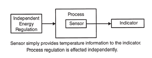
Fig 43: Open Loop System
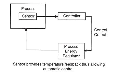
Fig 44: Closed Loop System
SENSOR CONSIDERATIONS WITH INSTRUMENTATION
Since most modern electronic (often microprocessor based) measuring and controlling instruments offer high accuracy and stability, great consideration must be given to the choice of temperature sensor to realise the performance potential. When specifying any system, a desired accuracy must be stated, and all components be considered accordingly. For example, the use of a low-cost base metal thermocouple with ±2.5°C short term accuracy is pointless if extra money is spent to procure a 0.1 °C accuracy controller when a 1°C accuracy instrument at lower cost would suffice.
Note however that the theoretical overall accuracy of a system is the sum of the individual accuracies of the system components. If a simple measurement system is structured as follows:
Nominal overall accuracy = accuracy of (thermocouple + transmitter + indicator)
e.g. Overall accuracy = ±2.5°C ±2°C ±1°C say Overall accuracy =±5.5°C worst case.
In practice, this figure may be pessimistic, e.g. If the actual realised accuracies are +2°C -1°C+0.5°C Respectively Actual accuracy at start up would be +1.5°C. However worst-case values must be borne in mind when specifying the components. It is clear from this example that is ordered to obtain good overall accuracy, the main emphasis must be places on optimising the sensor accuracy. For example by means of:
a) Specifying a calibrated sensor if necessary (this will define actual accuracy).
b) and/or specifying a higher accuracy sensor such as close tolerance version of either thermocouple or Pt100.
c) and/or specifying a Pt100 instead of a thermocouple if the application permits and if the instrumentation can be specified to suit.
d) Specifying a type of thermocouple with better basic accuracy and stability than say the standard type K. Examples are type T, N, R and S. However, suitability for the working temperature must be observed.
Note: Wiring and instrument input type must be considered when choosing the type of sensor.
TRANSMITTERS AND SIGNAL CONDITIONING
Temperature transmitters are widely used m measurement systems because their use allows long cable runs back to the associated instrumentation. They also perform a signal conditioning function.
A 2 wire temperature transmitter accepts a thermocouple or 3 wire Pt100 input and converts the “temperature” output into a 4-20mA current signal. The transmitter usually requires a 24Vdc supply which is connected in series with the 2 wire interface (or is provided by the host instrument). The amplified temperature signal can be transmitted via a long cable run if required, a considerable advantage with large site installations.
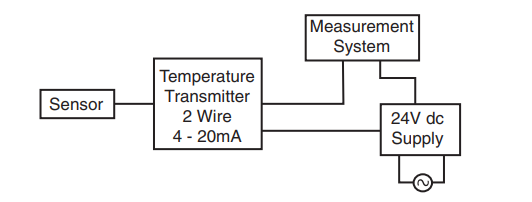
Fig 44a: Temperature Transmitter Circuit
The output can be either linear with temperature (usually the case with Pt100 inputs) or linear with thermocouple voltage (not linear with temperature - usually the case with thermocouple inputs). It is important to ascertain linearity or otherwise since this will have ramifications as far as the indicator is concerned, if the interface is non-linear with temperature, the indicator must display the appropriate transfer characteristic in order to give an accurate temperature readout (e.g. scaled for the Type K curve).
Transmitter scaling must be specified as required e.g. 0 to 400°C = 4 to 20mA. Remember this must correspond to the instrument scaling to avoid measurement errors. Input to output isolation is not necessarily incorporated as standard and it is essential to use electrically insulated sensors if isolation is not incorporated.
Signal conditioning is the process of modifying the raw input signal in one or more ways to facilitate communication and measurement. The transmitter is a simple form of signal conditioner, but signal conditioners usually provide linearisation scaling facilities and other functions. The most usual form of signal conditioner housing is a DIN rail mounting module.
Signal conditioners are particularly useful when different parameters are measured in a process (e.g. Pt100 and thermocouple outputs, flow rates, pressure, and force). The output from all the appropriate sensors or transducers can be rationalised into a common interface such as 4-20mA or 1-5V. Transfer characteristics can also usually be applied to suit a range of sensors and transducers resulting in a linear function. On this basis, standard process indicators can be used thus simplifying the instrumentation.
Programmable and so called “smart” transmitters effectively combine transmission and signal conditioning functions. In addition to manipulating the input-output function, a variety of transmission modes can be selected. Isolation of input to output further enhances their scope of applications; for example, a multi-sensor installation with individual transmitters can be used without danger of earth loops establishing spurious potentials. Programming is performed via a PC using software normally supplied or via a plug-in module.
INSTRUMENTATION & DATA COMMUNICATIONS & EMC
Many microprocessor-based indicators and controllers are user configurable for many thermocouple types and, in some cases for Pt100 as well. If the input type is not user selectable, it is essential that this is specified to suit the associated sensor. Ideally the sensor type should define the instrument, not vice versa; this is because the sensor must be chosen to suit the process. In practice, both should be considered to ensure optimum accuracy and cost-effectiveness.
Temperature Measurement & Control
Instrumentation for temperature measurement accept input signals directly or indirectly (via transmitters) from the sensor. The input requirements are different for the alternative signals, Pt100, thermistor, thermocouple, or transmitter. Indication can be either analogue (usually a drum scale or recorder chart) or digital and diverse options are available for the user to extend the functions beyond mere indication. Such options include single or multiple alarms and digital or analogue outputs (communications).
Single or multiple input instruments are available; for multi-channel inputs, selection can be either manual or automatic as with multiplexers and scanners. If isolation is not provided between inputs or between input and output the use of insulated (isolated) probes should be considered.
Scanning, logging, and data acquisition Systems are basically electronic measuring instruments with some form of input multiplexing and appropriate storage or retransmission of the measured temperatures. Alarm functions are usually incorporated. Section 7.3.2. provides more information.
Chart Recorders provide a hard copy record of process temperature often in addition to many other functions such as digital real-time displays and alarms. Such records are a legal requirement in some industries such as food and drug production. Sophisticated recorders have multi-channel capability and various analytical functions.
Temperature Alarms provide for indication of and some form of output switching in the event of the process temperature using above of falling below certain specified limits. They are used for process safety and product quality purposes, often as an adjunct to control systems by way of an independent “policeman.”
Where high precision thermometry is required, more expensive high accuracy instruments are available. Designed primarily for laboratory use, such indicators provide a high-resolution display of temperature and exceptionally good stability.
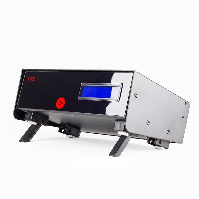
Fig 45: High Accuracy Digital Thermometer
Automatic Cold Junction Compensation
Temperature measurement instrumentation invariably incorporates some form of automatic cold junction compensation for thermocouple inputs. As described in Chapter 2, thermocouple measurements must be referred to a 0°C “cold” junction in order to give a true “hot” junction value. This is achieved in practice by incorporating a compensating circuit; this measures the actual ambient temperature (very rarely 0°C) at the thermocouple input terminals of the instrument and effectively adds the equivalent thermal e.m.f. to that of the thermocouple. This occurs continuously to compensate for both the value of ambient temperature and for its variations. The resulting indicated temperature is therefore a true representation of the process temperature.
The quality of this compensation is normally expressed as a rejection ratio or temperature coefficient. A rejection ratio of say 25:1 specifies that a 25°C change in ambient temperature would result in a 1°C change in indicated (measured) temperature. The higher the rejection ratio, the better the compensation. A figure of 20:1 to 25:1 is typical and usually adequate; higher performance instruments can achieve 75:1 or better. The stability may be expressed as say 0.05°C/°C which is equivalent to 20:1.
A temperature controller is effectively a combination of temperature indicator and added control board with some form of output circuit. The preceding Temperature Measurement copy is therefore applicable to this control explanation as far as indicators and measurement aspects are concerned.
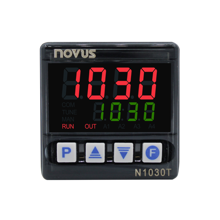
Fig 46: Temperature Controller
The principles of temperature control are treated in some depth in chapter 8 which should be referred to for an explanation of P.I. and D terms and more detail.
The addition of a control and output circuit to the measurement instrument permits closing of the loop to achieve closed loop automatic control of a process. Process energy can be derived from electricity, gas or oil and it is the function of the output stage to regulate it as appropriate.
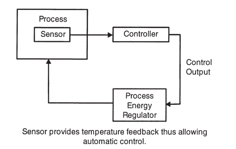
Fig 47: Closed Loop System
The diagram above illustrates a simple, single loop control system. Loops may be more complex, and many installations will use multi-loop configurations; however, the basic concept is the same.
The control circuit applies either on-off or a combination of proportional (P), integral (I) and derivative (D) functions as described in Chapter 8 to achieve the best possible control of process temperature. The output stage is instructed by the control circuit to apply or remove energy to or from the process accordingly by one of the various “switching” modes available.
Electrical energy is regulated via solid state switches (triacs; thyristors or solid-state relays) or via electromechanical relays or contactors. The actual switching device external to the controller in which case control signals are issued by the output circuit (e.g.0-1V, 4-20mA, logic signal or pulses).
Gas or oil are regulated by solenoid valves or proportional motorised valves and the controller issues electrical control signals to suit (voltage or current).
The process temperature is normally displayed digitally although some instruments provide some form of analogue indication (drum scale or deviation indication). The desired temperature (set-point) is set via analogue or digital adjustment.
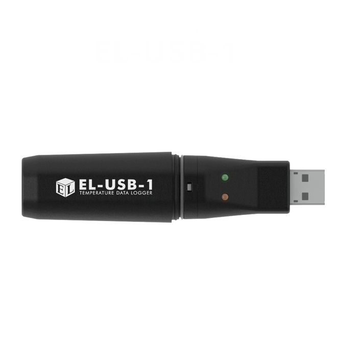
Fig 49: Data Logger
Data acquisition is the process of gathering data from a variety of transducers or sensors for monitoring, storage, or processing. A data logger is a stand-alone instrument for data gathering and storage. Logging is simply recording the data with a time/date stamp such that the data can be displayed, printed, analysed, and archived as required.
In the case of temperature, a typical application would be some form of experiment which involved any number of temperature sensors (e.g. thermocouples, resistance thermometers, thermistors). An event would require “collecting” measurements from any or all the sensors at a specified sampling rate for subsequent analysis. Data storage is especially important in long term projects.
When specifying a data acquisition system, considerations include the number and type of inputs and outputs, communications protocols, sampling speeds and data storage methods. Such a system can be “stand-alone” or a “front-end” for use in conjunction with a personal computer (PC). Digital printer or analogue chart recorders can be used to print-out data either on a real-time basis or from stored data.
The chosen sampling rate (the rate at which signals from the input transducers are scanned and acquired) needs to be consistent with the dynamics of the process, response times of the transducers and the multiplexing capability of the system.
In the case of remote sensing such as on a large site, radio telemetry is often used to transmit the measured data to the data acquisition system. Supervisory Control and Data Acquisition (SCADA) systems monitor and record data in the same way but additionally are programmed for real-time, on-line decision making, process control activity and alarm monitoring.
Data Communications & Analogue Retransmission
Analogue Outputs from measuring and control instruments are not data communications in the strict definition of the term. However, analogue (retransmission) signals are commonly used for outputting the scaled and amplified process variable to chart recorders and data loggers. Such signals are typically 0-1V dc or 4-20mA dc.
Data Communication is used for transferring data and instructions between associated instruments or between instruments and computers, usually PCs.
Data characters are represented by a data code, each element of which consists of a group of binary digits (bits) each being 1 or 0. The group of bits is called a byte or word. The task of data transmission is to send bytes from one point to another (e.g. instrument to PC).
Data communication is performed as either serial or parallel communication depending on the configuration provided by the indicator or controller and/or the requirements of the application. Parallel communication refers to data bits transmitted via separate lines for each bit and therefore utilizes several wires (an 8-bit word requires 8 lines).
Serial Communication refers to data bits transmitted serially through a single line and therefore utilizes a single pair of wires. Examples of widely used recommended standard (RS) include RS-232C, RS-422A and RS-485.
a) RS-232C is the most common standard as specified by EIA (Electronics Industries Association). It is used for interfacing between data terminal equipment and data communications equipment. A maximum line length of 15m is permitted. It is a single, bi-directional serial interface.
b) RS-422A, another EIA standard, specifies a low impedance differential signal permitting a line length of around 1200m. It is a single, bi-directional serial interface.
c) RS-485 is another EIA standard which specifies the interface characteristics but allows the equipment designer to choose the desired protocol. This enables users to configure multi-drop and local area network communications to suit different applications. It is a multi-drop, bi-directional, serial interface with a capacity of up to thirty-two transmit / receive drops per line. Developments of serial data communications for industrial applications include HART, MODBUS and other examples developed by leading manufacturers.
HART (Highway Addressable Remote Terminal) is used with “smart,” analogue process control instruments for example. MODBUS is an alternative versatile, industrial networking system.
For more information on digital communications, the Institute of Measurement & Control can supply details of a wide range of suitable publications.
Electro-Magnetic Compatibility (EMC)
EMC Requirements for Electrical Equipment for Measurement, Control and Laboratory Use.
Temperature instruments in common with all types of instrumentation must comply with European EMC (Electro-Magnetic Compatibility) regulations in terms of electromagnetic radiation if they are to be available in the European market. The regulation in question is IEC 1326-1. Accordingly, CE marking which indicates compliance, is mandatory.
The regulation is basically that electrical / electronic equipment must not generate significant amounts of electromagnetic radiation (including r.f.i) nor be sensitive to its effects. Standards published accordingly define the requirements, test procedures and various aspects covering both emission and immunity.
Equipment within the scope of the regulations can be subjected to electromagnetic disturbances (EMI), conducted by measurement or control lines, or radiated from the environment. The types and levels of disturbances depend on the prevailing conditions in which the equipment operates. Such equipment can also be a source of electromagnetic disturbance over a wide frequency range; again, such energy can be conducted through signal lines or directly radiated, and this can affect other equipment. Emissions must be minimized to ensure that interference with normal operation of other equipment does not occur. EMC defines three basic aspects of interference.
a) A source which generates an interference signal
b) A recipient which is adversely affected by the signal
c) A path which carries the signal
Interference can be INTRASYSTEM where each aspect is in a separate system. Interference sources can be various inform – natural, man-made intentional (e.g. radio waves) and unintentional (e.g. power lines). Similarly recipients can be either intended or unintended.
The path can be conduction or radiation or a combination of both. The key elements are defined as:
EMC Electro-Magnetic Compatibility. The condition which exists when a piece of electrical equipment neither malfunctions nor causes malfunction in other equipment when operating in surroundings for which it was designed.
EMI Electro-Magnetic Interference. The unintentional interaction between a piece of electrical equipment and its electromagnetic surroundings.
Can’t find what you need? Call or email our technical sales team on
+44 (0) 1243 871 280 or sales@labfacility.com for help with product selection and technical support