Resistance Thermometer (RTD) Theory and Practice
RESISTANCE THERMOMETER (RTD) THEORY AND PRACTICE
ADOPTION OF Pt100 THERMOMETERS
RESISTANCE THERMOMETER PRACTICE
RESISTANCE THERMOMETER INSTALLATION AND APPLICATION
- Sheathed Resistance Thermometers – Pt100 Sensing Resistors
- Connecting Resistance Thermometers to Instruments
- Performance Considerations When Using Resistance Thermometers
- Surface Temperature Measurement
- High Accuracy Measurement
NTC THERMISTORS & INFRARED (NON-CONTACT) SENSORS
INFRARED TEMPERATURE MEASUREMENT
RESISTANCE THERMOMETER THEORY AND PRACTICE
The electrical conductivity of a metal depends on the movement of electrons through its crystal lattice. Due to thermal excitation, the electrical resistance of a conductor varies according to its temperature, and this forms the basic principles of resistance thermometry. The effect is most exhibited as an increase in resistance with increasing temperature, a positive temperature coefficient of resistance.
When utilising this effect for temperature measurement, a large value of temperature coefficient (the greatest possible change of resistance with temperature) is ideal; however, stability of the characteristic over the short and long term is vital if practical use is to make of the conductor in question. The relationship between the temperature and the electrical resistance is usually non-linear and described by a higher order polynomial:
R(t) = R° (1 + A:t + B:t2 + C:t3 +……)
where R° is the nominal resistance at a specified temperature. The number of higher order terms considered is a function of the required accuracy of measurement. The coefficients A, B and C etc. depend on the conductor material and basically define the temperature -resistance relationship.
Materials most utilised for resistance thermometers are Platinum, Copper and Nickel. However, Platinum is the most dominant material internationally.
Platinum sensing resistors are available with alternative R° values, for example 10, 25 and 100 Ohms. A working form of resistance thermometer sensor is defined in IEC and DIN specifications, and this forms the basis of most industrial and laboratory RTD temperature sensors. The platinum sensing resistor, Pt100 to IEC 60751 is dominant RTD sensor in Europe and in many other parts of the world. Its advantages include chemical stability, relative ease of manufacture, the availability of wire in a highly pure form and excellent reproducibility of its electrical characteristic. The result is a truly interchangeable sensing resistor which is widely commercially available at a reasonable cost.
This specification includes the standard variation of resistance with temperature, the nominal value with the corresponding reference temperature, and the permitted tolerances. The specified temperature range extends from -200 to 961.78°C. The series of reference values is split into two parts: -200 to 0°C and 0 to 961.78°C.
The first temperature range is covered by a third order polynomial
R(t) = R°(1 + A.t + B.t2 + C. [t – 100°C] .t3)
For the range 0 to 850°C there is a second-order polynomial
R(t) = R°(1 + A.t + B.t2)
The coefficients are as follows:
A = 3.9083 x 10⁻³ . °C-1
B = -5.775 x 10⁻⁷ . °C-2
C = -4.183 x 10⁻¹² . °C-4
The value R° is referred to as nominal value or nominal resistance and is the resistance at 0°C. According to IEC 751 the nominal value is defined as 100.00 Ohm, and this is referred to as a Pt100 resistor. Multiples of this value are also used; resistance sensors of 500 and 1000 Ohm are available to provide higher sensitivity, i.e., a larger change of resistance with temperature.
The resistance changes are approximately:
0.4 Ω/°C for the Pt100
2.0 Ω/°C for the Pt500
4.0Ω/°C for the Pt 1000
An additional parameter defined by the standard specification is the mean temperature coefficient between 0 and 100°C. It represents the mean resistance change referred to the nominal resistance at 0°C:
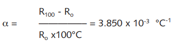
Note: For exact calculation use = 0.00385055°C-1
R100 is the resistance at 100°C, R° at 0°C. The resistance change over the range 0°C to 100°C is referred to as the Fundamental Interval.
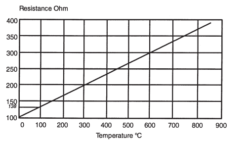
Fig 14: Resistance/Temperature Characteristics of Pt100
The very high accuracy demanded of primary standard resistance thermometers requires the use of a purer form of platinum for the sensing resistor. This results in different R° and alpha values. Conversely, the platinum used for Pt100 sensor versions is “doped” to achieve the required R° and Alpha values.
ADOPTION OF Pt100 THERMOMETERS
The practical range of Pt100 sensor based thermometers extends from -200°C to 650°C although special versions are available from up to 962°C. Their use has in part taken over from thermocouples in many applications for a variety of reasons:
a) Installation is simplified since special cabling and cold junction considerations are not relevant. Similarly, instrumentation considerations are less complex in terms of input configuration and enhanced stability.
b) Instrumentation developments have resulted in high accuracy, high resolution and high stability performance from lower cost indicators and controllers; such accuracy can be better exploited using superior temperature sensors.
c) The availability of a growing range of sensing resistor configurations has greatly expanded the scope of applications; such configurations include miniature, flat-film fast response versions in addition to the established wirewound types with alternative tolerance bands.
The usable maximum temperature of the sensing resistor is dependent on the type of sheath material used to provide protection. Those using stainless steel should not exceed 500°C because of contamination effects. Nickel and Quartz are alternative choices allowing higher operating temperatures.
RESISTANCE THERMOMETER (RTD) PRACTICE
Terminating the Resistance Thermometer
Fundamentally, every sensing resistor is a two-wire device. When terminating the resistor with extension wires, a decision must be made as to whether a 2,3 or 4 wire arrangement is required for measurement purposes.
In the sensing resistor, the electrical resistance varies with temperature. Temperature is measured indirectly by reading the voltage drop across the sensing resistor in the presence of a constant current flowing through it using Ohm's Law: V = R.I
The measuring current should be as small as possible to minimise sensor heating; a maximum of around 1mA is regarded as acceptable for practical purposes. This would produce a 0.1V drop in a Pt100 sensing resistor at 0°C; the voltage dropped which varies with temperature is then measured by the associated circuitry. The interconnection between the Pt100 sensor and the associated input circuit must be compatible with both and the use of 2,3 or 4 wires must be specified accordingly.
It is essential that in any RTD temperature sensor the resistance value of the external lead wires be considered, and if this value affects the required accuracy of the thermometer, its effect should be minimised.
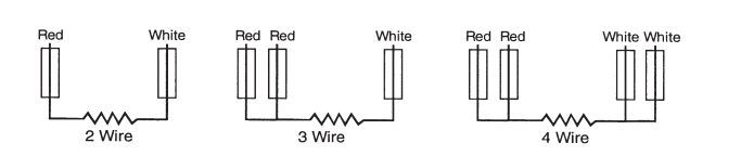
This is usually accomplished by connecting the lead wires into the modified WHEATSTONE BRIDGE circuit in the measuring instrumentation. The lead wires for a RTD temperature sensor can be 2,3 or 4 in number, often dependent upon the requirements of the instrumentation and/or the overall accuracy required. Two leads are adequate for some industrial applications, three leads compensating for lead resistance improves accuracy, and for the highest accuracy requirements four leads are required, in a current/voltage measuring mode. Typical bridge circuits for 2, 3 and 4 lead thermometers are shown below:
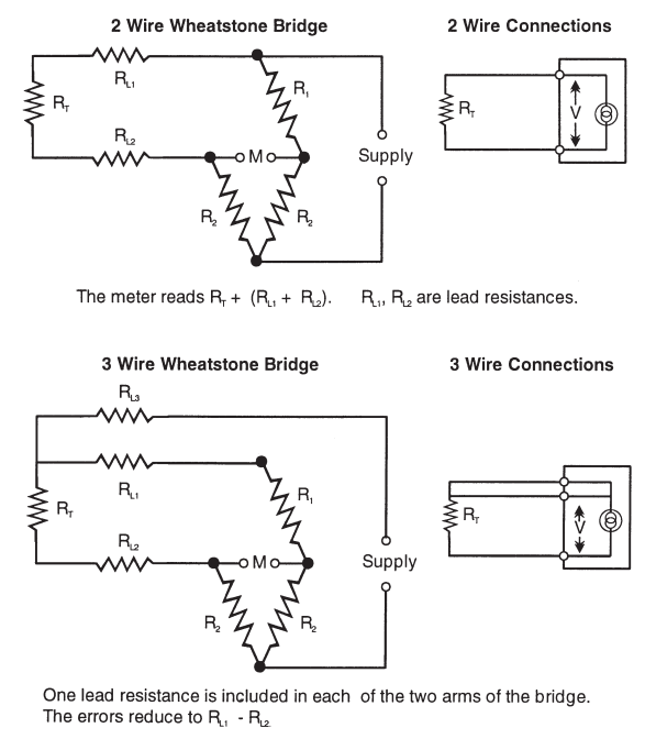
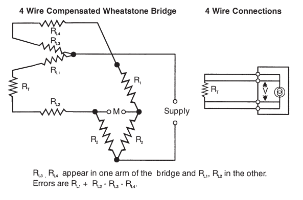
Fig 15: Practical Bridge Circuits for 2, 3 and 4 Wire Thermometers.
The connection between the RTD temperature sensor and the instrumentation is made with standard electrical cable with copper conductors in 2,3 or 4 core construction. The cabling introduces electrical resistance which is places in series with the resistance thermometer. The two resistances are therefore cumulative and could be interpreted as an increased temperature if the lead resistance is not allowed for. The longer and/or the smaller the diameter of the cable, the greater the lead resistance will be, and the measurement errors could be appreciable. In the case of a 2-wire connection, little can be done about this problem and some measurement error will result according to the cabling and input circuit arrangement.
For this reason, a 2-wire arrangement is not recommended. If it is essential to use only 2 wires, ensure that the largest possible diameter of conductors is specified, and that the length of cable is minimised to keep cable resistance to as low a value as possible.
The use of 3 wires, when dictated either by probe construction or by the input termination of the measuring instrument, will allow for a good level of lead resistance compensation. However, the compensation technique assumes that the resistance of all three leads is identical and that they all reside at the same ambient temperature; this is not always the case. Cable manufacturers often specify a tolerance of up to ±15% in conductor resistance for each core making accurate compensation impossible. Additional errors may result from contact resistance when terminating each of the 3 wires. A 3-wire system cannot therefore be relied upon for total accuracy.
Optimum accuracy is therefore achieved with a 4-wire configuration. The Pt100 sensor measuring current is obtained through the supply. The voltage drop across the sensing resistor is picked off by the measurement wires. If the measurement circuit has a very high input impedance, lead resistance and connection contact resistances have negligible effect. The voltage drops thus obtained is independent of the connecting wire resistivity. In practice, the transition from the 2 wires of the Pt100 to the extension wires may not occur precisely at the element itself but may involve a short 2 wire extension for reasons of physical construction; such an arrangement can introduce some error, but this is usually insignificant.
Note: The wiring configuration (2,3, or 4 wire) of the thermometer must be compatible with the input to the associated instrument.
The problems of the 2 or 3 wire configuration as described can be resolved in large part by using a 4-20mA transmitter. If the transmitter is located close to the Pt100 sensor, often in the terminal head of the thermometer, then the amplified “temperature” signal is transmitted to the remote instrumentation. Cable resistance effects are then not applicable other than those due to the relatively short lead wires between the sensor and transmitter.
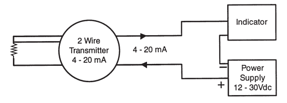
Fig 16: Temperature Transmitter – 2 Wire Loop. Input Pt100, 3 Wire
Most transmitters use a 3-wire input connection and therefore provide compensation for lead resistance.
RESISTANCE THERMOMETER INSTALLATION (RTD) AND APPLICATION
Sheathed Resistance Thermometers – Pt100 Sensor Resistors
A variety of sheath materials is used to house and protect the alternative types of sensing resistor to make Pt100 probes; sheath materials are described in a separate chapter.
The resistance element is produced in one of two forms, either wire-wound or metal film. Metal film resistors consist of a platinum layer on a ceramic substrate; the coil of a wire wound version is fused into ceramic or glass.
a) Wire – wound resistors.
The construction of the wire wound platinum detector uses a large proportion of manual labour, with a high degree of training and skill. The careful selection of all components is vital, as are good working conditions. Complete compatibility between metal, ceramic and glass when used, together with the connecting leads is essential, and most important, strain must be eliminated. Various methods of detector construction are employed to meet the requirements of differing applications. The unsupported “bird cage” construction is used for temperature standards, and the partially supported construction is used where a compromise is acceptable between primary standards and use in industrial applications. Other constructional methods include the totally supported construction which can normally withstand vibration levels to 100g, and the coated wire construction where the wire is covered with an insulating medium such as varnish. The maximum operating range of the latter method is limited by the wire coating to usually around 250°C.
Of the differing methods of construction described, the partially supported construction is the most suited for industrial applications where high accuracy, reliability and long-term stability are required. The wire is wound into a small spiral and inserted into axial holes in a high purity alumina rod. A small quantity of glass adhesive is applied to these holes, which after firing secures a part of each wire into the alumina. Detectors have been produced by this method as thin as 0.9mm diameter and as short as 6mm with a resistance accuracy of ±0.01%. A host of other sizes and shapes are produced and used in Pt100 RTD temperature sensor manufacturing. The internal leads of a detector assembly should be constructed of materials dictated by the temperature the assembly will have to withstand. Up to 150°C and 300°C silver leads are preferred, from 300°C to 500°C nickel leads are considered best although the resistance tends to be high, and above 550°C noble metal leads prove most satisfactory.
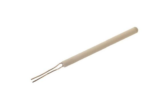
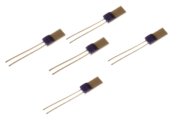
Fig 17: detectors
b) Flat Film Resistors
Flat film are resistant to shock and have quick thermal response times compared to wirewound detectors.
Connecting RTD Temperature Sensors to Instruments
Unlike thermocouples, resistance thermometers do not require special cable and standard electrical wires with copper conductors should be used. The heavier the gauge of the conductors, the less the impact is on errors due to lead resistance effects as described. Typically, 7/0.2mm or 14/0.2mm conductors are specified with insulation chosen to suit a particular application. Refer to “Terminating the Resistance Thermometer on page 27 for details of the different wiring configurations (2,3 or 4 wire).
Recommended Colour Codes BS EN 60751:1996
Installation Notes:
a) Always observe colour codes and terminal designations; the wiring configuration of the thermometer must match that of the instrument input arrangement.
b) Avoid introducing “different” metals into the cabling; preferably use copper connecting blocks or colour coded (or other dedicated) connectors for the greater accuracy, reliability and convenience of installation.
c) Use screened or braided cable connected to ground in any installation where ac pick-up or relay contact interference is likely.
d) For very long cable runs, ensure that cable resistance can be tolerated by the instrumentation without resulting in measurement errors. Modern electronic instruments usually accept up to 100 Ohms or so for 3 or 4 wire inputs. Refer to the relevant instrument specifications for full details.
e) Cabling is usually available with many different types of insulation material and outer covering to suit different applications. Choose carefully in consideration of ambient temperature, the presence of moisture or water and the need for abrasion resistance.
f) If errors occur, be sure to check the sensor, the cable, interconnections, and the instrument. Many such problems are due to incorrect wiring or instrument calibration error rather than the sensor.
Interchangeability is facilitated using plug and socket interconnections. Special connectors are available for this purpose.
Guide to Cable Insulation and Coverings
|
Which insulation Material? |
Usable Temperature Range |
Application Notes |
|
PVC |
-10°C to 105°C |
Good general-purpose insulation for “light” environments. Waterproof and very flexible. |
|
PFA (extruded) |
-75°C to 250°C |
Resistant to oils, acids other adverse agents and fluids. Good mechanical strength and flexibility. PTFE better for steam/elevated pressure environments |
|
PTFE (taped & wrapped) |
-75°C to 250/300°C |
Resistant to oils, acids other adverse agents and fluids. Good mechanical strength and flexibility. |
|
Glassfibre (varnished) |
-60°C to 350/400°C |
Good temperature range but will not prevent ingress of fluids. Fairly flexible but does not provide good mechanical protection. |
|
High temperature glass fibre |
-60°C to 700°C |
Will withstand temperature up to 700°C but will not prevent ingress of fluids. Fairly flexible, not good protection against physical disturbance. |
|
Ceramic Fibre |
0 to 1000°C |
Will withstand high temperature, up to 1000°C. Will not protect against fluids or physical disturbance. |
|
Glassfibre (varnished) stainless steel overbraid |
-60°C to 350/400°C |
Good resistance to physical disturbance and high temperature (up to 400°C). Will not prevent ingress of fluids. |
Performance Considerations When Using Resistance Thermometers
There are various considerations appropriate to achieving good performance from resistance thermometer (Pt100) sensors:
a) Length of cable runs and loop resistance – Refer to Installation Notes
b) Interference and Isolation
With long cable runs, the cables may need to be screened and earthed at one end (at the instrument) to minimise noise pick-up (interference) on the measuring circuit.
Poor insulation is manifested as a reduction in the indicated temperature, often because of moisture ingress into the probe or wiring.
c) Self-heating
To measure the voltage dropped across the sensing resistor, a current must be passed through it. The measuring current produces dissipation which generates heat in the sensor. This results in an increased temperature indication. There are many aspects to the effects of self-heating but generally it is necessary to minimise the current flow as much as possible; 1mA or less is usually acceptable. The choice of current value must take into account the R° value of the sensing resistor since dissipation = I2R.
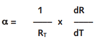
If the sensor is immersed in flowing liquid or gas, the effect is reduced because of more rapid heat removal. Conversely, in still gas for example, the effect may be significant. The self-heating coefficient E is expressed as:
E = ▲t/(R – I2)
where ▲t = (indicated temperature) – (temperature of the medium)
R = Pt resistance
I = measurement current
d) Stem conduction
This is the mechanism by which heat is conducted from or to the process medium by the Pt100 probe itself; an apparent reduction or increase respectively in measured temperature results. The immersion depth (the length of that part of the probe which is directly in contact with the medium) must be such as to ensure that the “sensing” length is exceeded (double the sensing length is recommended). Small immersion depths result in a large temperature gradient between the sensor and the surroundings which results in a large heat flow.
The ideal immersion depth can be achieved in practice by moving the probe into or out of the process medium incrementally; with each adjustment, note any apparent change in indicated temperature. The correct depth will result in no change in indicated temperature.
For calibration purposes 150 to 300mm immersion is required depending on the probe construction.
The use of thermowells increases the thermal resistance to the actual sensor; heat also flows to the outside through the thermowell material. Direct measurements are preferable for good response and accuracy but may be mechanically undesirable.
Low flow rates or stationary media result in reduced heat transfer to the thermometer; maximum flow rate locations are necessary for more accurate measurement.
Surface Temperature Measurement
Resistance thermometers are mainly stem sensing devices with a finite sensing length and as such are best suited to immersion use. However, certain types of sensing resistors can be applied to surface sensing when suitably housed. Thin film devices and miniature wire-wound elements can be used in a surface contact assembly such as those shown below. In such cases, the sensing devices must be held in close contact with the surface whilst being thermally insulated from the surrounding medium. Rubber and PTFE bodies are often utilised for such assemblies. Locating the device on a surface can be achieved in various ways including the use of an adhesive patch and pipe clips. If it is possible to provide lagging (thermal insulation) around the sensor assembly, accuracy will be improved.
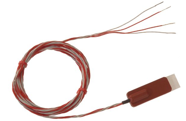
Fig 18: Self Adhesive Patch Pt100 Sensor for Surface Temperature Sensing
Assuming a 3 or 4 wire connection, and the use of a class B sensing resistor (refer to page 83 for tolerance details), a standard thermometer assembly will provide an accuracy of around 0.5°C between 0°C and 100°C. Considerable improvement on this figure can be achieved by various means including the use of closer tolerance sensors. Reference to the tolerance chart on page 83 will indicate “accuracies” of the standard Class B and Class A devices. However, tolerances of 1⁄3, 1⁄5 and 1⁄10 of the Class B values are available with wirewound and other resistors and these allow for higher precision of measurement. It is important to note that these tolerances are rarely achieved in practice due to stress and strain in handling and assembly, extension lead wire effects and thermal considerations. However, the closer tolerances do provide more precise basic accuracy platforms. Practical overall accuracy of around 0.15°C can be achieved between 0°C and 100°C if a 1⁄10DIN RTD sensor is used.
Tolerance (+) per °C
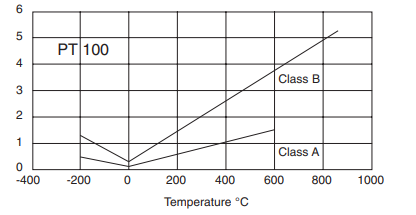
Fig 19: Pt100 Tolerances
System (Pt100 probe and instrument) accuracy can be optimised by means of calibration and certification which identifies overall measurement errors; such calibrations are usually carried out to international standards.
High precision resistance thermometers are available for laboratory use and accuracies of a few millidegrees can be achieved using such devices. These may use different alpha values and must be calibrated at fixed points. Nominal 10, 25 and special 100 Ohm Ro versions may be used.
NTC THERMISTORS & INFRARED (NON-CONTACT) SENSORS
The NTC Thermistor is an alternative to the Platinum resistance thermometer; the name derives from “thermal resistor” and defines a metallic oxide which displays a high negative temperature coefficient of resistance. This compares with the small positive coefficient of say Platinum used for the Pt100 sensor. The temperature-resistance characteristic of the thermistor is up to 100 times greater than that of the alternative resistance thermometer and provides high sensitivity over a limited temperature range.
PTC (Positive Temperature Coefficient) versions are also available, but their use is much less common than the popular NTC types.
High resistance thermistors, greater than 100kOhms are used for high temperatures (150 to 300°C); devices up to 100kOhms are used for the range 75 to 150°C. Devices below 1kOhm are suitable for lower temperatures, -75 to +75°C.
Thermistors provide a low-cost alternative to the Pt100 although the temperature range is limited; interchangeability and accuracy place them between Pt100 and thermocouple alternatives. Since their resistance value is relatively high, a simple 2 wire connection is used.
Resistance / Temperature Characteristic
The electrical resistance of a NTC (Negative Temperature Coefficient) Thermistor, decreases non-linearly with increasing temperature.
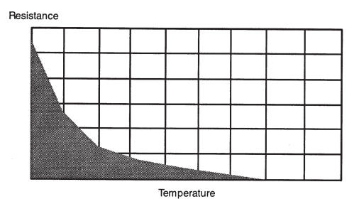
Fig 20: Resistance/Temperature Characteristics of NTC Thermistor
The amount of change per degree Celsius (C) is defined by either the BETA VALUE
(Material constant), or the ALPHA COEFFICIENT (resistance temperature coefficient).
The Beta Value is defined by:
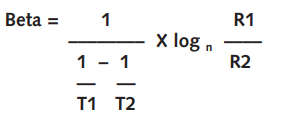
where T1 and T2 are two specified temperatures, usually 273.15K (0°C) and 323.15K (50°C), and R1 over R2 is the ratio of the measured resistance at the two specified temperatures. Beta is expressed in degrees Kelvin.
The Alpha Coefficient is defined by:
where T is specified temperature in degrees K, R is resistance at specified temperature T. Alpha value is usually expressed in % per °C. There is a direct relationship between the Alpha Coefficient and the Beta Value.
The larger the Alpha or Beta Value, the greater the change in resistance per °C, (the greater the sensitivity). Within the thermistor industry, a thermistor material system is usually identified by specifying the Alpha coefficient, Beta Value, or the ratio between the resistance at two specified temperatures (typically, RO/R50, R25/R125, RO/R25, R70/R25, or RO/R70).
Electrical Resistivity (Ohm-cm) is one electrical characteristic of different materials. It is equal to the resistance to current flow of a centimetre cube of a particular material when the current is applied to two parallel faces. It is defined by the following equation:
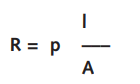
where R is resistance, l is length of a uniform conductor, A is cross-sectional area, and p is resistivity.
When comparing different thermistor materials, the material with the larger Alpha or Beta value will generally have the larger resistivity.
Material resistivity is an important consideration when choosing the proper thermistor for an application. The material must be chosen such that a thermistor chip of a specified resistance value will not be too large or too small for a particular application. Thermistor materials are available with a variety of resistivity values. The resistance of an NTC thermistor is determined by material resistivity and physical dimensions. Required resistance value is usually specified at 25°C.
At low measuring current levels, the power dissipated by a thermistor is small and is of little consequence to measurement accuracy. Increased current results in increased dissipation causing the sensor to heat up; an increased temperature is indicated resulting in measurement errors.
General
Probe construction and connection to instruments are as for resistance thermometers but only a 2-wire arrangement is used (lead resistances will be very small compared with sensor resistance).
INFRARED TEMPERATURE MEASUREMENT
Principles of Infrared Sensing
Energy is radiated by all objects having a temperature greater than absolute zero (-273°C). The energy level increases as the temperature of the object rises.
Therefore, by measuring the level of the energy radiated by any object, the temperature of that object can be obtained. For this purpose, energy in the infrared band is used (wavelengths of between 0.5 micron and 20 micron are observed in practice). Emissivity has to be taken into account when evaluating the temperature using infra-red radiation (described below).
The two most common methods of sensing and measuring temperature on a non-contact, infrared basis are:
a) Optical pyrometry
b) Non-contact thermocouple
Optical pyrometry uses comparison techniques to measure temperature; non-contact thermocouple techniques provide an accurate, convenient and relatively inexpensive alternative.
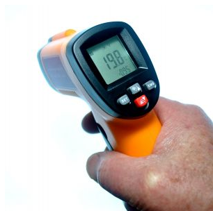
Fig 20a: Infrared Digital Thermometer
Infrared thermocouples are passive devices which provide a “true” thermocouple output signal appropriate to the type specified (usually type J or type K). Such sensors can therefore be directly connected to the thermocouple input of an instrument but, unlike the standard thermocouple provide convenient, non-intrusive, remote temperature sensing. This approach is usually inexpensive, especially when compared with optical systems. The compact dimensions of these devices make them as convenient as a thermocouple to install in industrial processes or to use in experiments; handheld sensors are also available.
The detection method used by many infrared thermocouples is similar in principle to that of optical systems, the thermopile. A thermopile consists of an array of thermocouple junctions arranged in a high-density series matrix; heat energy radiated from the object results in an “amplified” output from the sensor (i.e. a multi-thermojunction signal as opposed to that of a single junction).
The output is scaled to correspond to that of the specified thermocouple type (e.g., approx. 40µV/°C for type K over a limited and reasonably linear range).
Since the sensor receives only infrared radiation energy, the rules of thermal radiation apply and such things as non-linearity and emissivity must be considered.
Linearity: Over a restricted temperature range, the sensor output is sufficiently linear to produce a signal which emulates that of the thermocouple with reasonable accuracy; an accuracy of around 2% can be achieved for a type K non-contact sensor over the range 50°C to 650°C for example.
Emissivity: Emissivity is a parameter which defines how much radiation an object emits at a given temperature compared with that of a black body at the same temperature. A black body has an emissivity of 1.0; there is no surface reflection and 100% surface emission.
The emissivity of a surface is the percentage of the surface which emits; the remaining percentage of the surface reflects. The percentage though, is expressed as a coefficient hence 100% equivalent to 1.0. All values of emissivity fall between 0.0 and 1.0.
For accurate measurement of different materials, ideally, the emissivity should be considered, and correction applied. Simple instruments may not allow for this, but more sophisticated alternatives incorporate emissivity adjustment.
Other considerations include sensor to object distance / target area considerations and the possible need for sensor cooling in high temperature applications.
Can’t find what you need? Call or email our technical sales team on +44 (0) 1243 871 280 or sales@labfacility.com for help with product selection and technical support